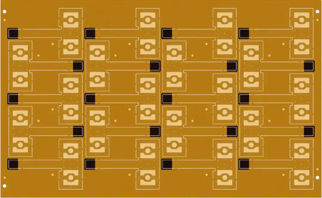

The shape of FPC is mostly irregular and its size is relatively small. It is usually recommended to use the panning process for production to improve the utilization rate of the boards.
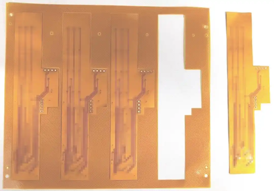
The base material of FPC is PI or PET, which is thin, light and flexible. Unlike PCB, it cannot achieve SET assembly through V-CUT or stamp holes. Instead, it uses a method of cutting and retaining connection points to achieve SET assembly.
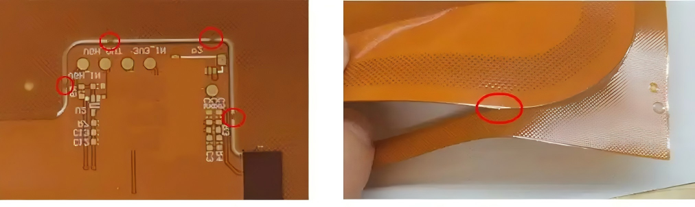
However, if the edge of FPC is not copper-clad, it will be very thin. If connection points are designed in this area, during manual separation, it is very easy to tear the board or break the fine lines on the edge, resulting in an increase in the defect rate of board separation.
So, how can we improve the yield of FPC separation? Adding one anti-tear line can easily achieve FPC separation!and What is tear-resistant wire?
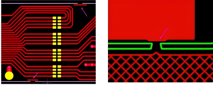
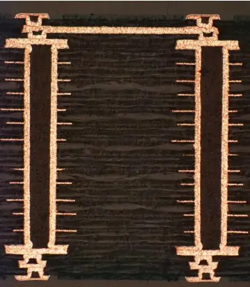
Anti-tear wire refers to adding a small copper wire to the corresponding line layer at the connection point. By enhancing the strength of the connection point area, it can effectively prevent the risk of FPC being torn during manual board separation. If space permits, it is recommended to add tear-resistant wires to both outer layers of the circuit.
What are the requirements for designing tear-resistant lines?
Engineers can choose to design the tear-resistant wire themselves or ask us to do it for them.
When designing, please pay attention to following the following norms
(1) Is the anti-tear wire added to the double-sided circuit layer? Will the assessment have any impact on the original route? It is not recommended to increase the position of the antenna.
(2) The anti-tear line should be designed inside the board and be 0.1mm away from the center of the forming line
(3) The anti-tear wire may have copper exposed on the side. It is necessary to consider whether it will have an impact on the product?
(4) The anti-tear wire should be 0.1mm away from the normal lines inside the board. If the edge of the board is ground copper, it can be connected to the ground copper.
(5) The line width should be at least 0.15mm, and the length should be at least 0.5mm longer than each end of the connection point.